
The Mercury Gate: An Electromagnetic Metro for the Solar System
A hard-science engineering estimate: from the Earth–Mercury transport problem to the limits of electromagnetic braking, the geometry of a gate chain, recoil, energy storage and landing
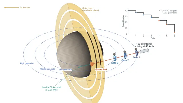
One Mercury Gate chain: six gates on four orbits take a 100 t container from 40 km/s down to a 50 km orbit.
In 2137 the outpost on Mercury is running, but it is still more than a century away from supporting itself. Equipment and feedstock have to come from Earth, and a conventional cargo mission to Mercury takes about seven years. In Solar Express, Scienshell's answer is the Mercury Gate: take the job of speeding up and slowing down away from the ship and put it in orbit instead. The film calls the Mercury Gate the first-generation prototype of the later star gates.
This article follows the idea from the transport problem to the hard limits of electromagnetic braking, then to the geometry of the gate chain, the recoil on the gates, energy storage and the landing on the ground. The calculations are order-of-magnitude engineering estimates. Each key number is labelled as a measurement, an assumption, a calculation or part of the film's setting.
The reasoning rests on three layers:
- Established physics (not negotiable): orbital mechanics, conservation of momentum, kinematics (braking distance equals the difference of the squared speeds divided by twice the deceleration), magnetic pressure, Lenz's law, and the virial limit on superconducting energy storage.
- Extrapolated present-day technology (adopted as setting): coilguns and electromagnetic launchers, superconducting magnetic energy storage (SMES), and the orbit-rebalancing logic of momentum-exchange tethers (MXER).
- Engineering extrapolation (setting): superconducting main rings of a few thousand tonnes, rock counterweights of about a million tonnes, and standard containers rated for 1,000 g.
The main findings
Why go fast. A conventional mission takes about seven years. With the Mercury Gate a ship can fly a direct trajectory of about 40 days, but it arrives at about 40 km/s and must then lose about 37 km/s in one go. A 40 km/s arrival is what the cheapest-departure 40-day trajectories actually give.
Braking distance sets the floor. Going from 40 km/s to 3 km/s needs about 8,100 km of track at 10 g and about 81 km at 1,000 g. At 10 g the braking would last more than six minutes, which no crew could sustain. So the Mercury Gate is first of all a freight system: six gates, each with a braking corridor about 13 km long, put roughly 1,000 g on an overload-rated container.
Each gate swallows one container's worth of energy. A 100 t container gives up about 1.3×10¹³ J at each gate. Because the gates themselves are moving, what reaches the coils is 0.92–1.30×10¹³ J, below the roughly 2×10¹³ J that a 1,500 t superconducting main ring can hold.
Recoil is absorbed by counterweights and two-way traffic. A rock counterweight of about a million tonnes keeps each kick to a change of about 2–5 km in orbit height. Arrivals push the gates up, departures push them down.
Six gates on one straight approach line. The last gate sits where the line touches a 50 km parking orbit, so the container leaves it at exactly orbital speed.
Living with the solar rings. The two middle gate orbits pass through the 200 km gaps between the solar rings from the earlier film. The innermost ring starts at 100 km, so the three lowest gates fly at about 50 km, safely below it (Section 6).
Table 1. Engineering baseline
| Parameter | Value | Basis |
|---|---|---|
| Standard container | 100 t, long cylinder about 10 m across, wrapped in superconducting coils | Setting (film storyboard) |
| Arrival speed / orbital insertion speed | About 40 km/s / 2.97 km/s (50 km altitude) | Calculation |
| Gate chain | 6 gates, each removing the same share of the squared speed | Setting |
| Braking corridor | 9.4–13.2 km per gate at about 1,000 g; field about 5.6 T | Calculation |
| Main ring | 1,500 t superconducting coil, storing up to about 2×10¹³ J | Setting / calculation |
| Counterweight | About 1 million tonnes of Mercurian rock | Setting |
| Gate orbits | 4 levels: about 50 / 1,300 / 2,300 / 3,500 km altitude | Setting (fitted around the solar rings) |
| System size | 24 gates in 4 chains | Setting |
| Ground braking tunnel | 50 km, about 9 g, about 34 s | Calculation |
1. Why a conventional mission takes seven years
Mercury is close to the Sun, so getting there from Earth means falling deep into the Sun's gravity well. A Hohmann transfer takes about 105 days, but it arrives with about 9.6 km/s of excess speed relative to Mercury (calculation, circular coplanar orbits). Getting captured means burning a great deal of propellant. MESSENGER and BepiColombo therefore used repeated planetary flybys to shed speed gradually. MESSENGER needed 6.6 years from launch to orbit insertion; BepiColombo, launched in 2018, was scheduled to arrive in late 2026, about eight years later (measurement).
If the braking does not have to be done by the ship, the ship can take the fast road. Figure 1 shows the trade-off. For a fixed trip time there is a family of trajectories: leave Earth slowly and arrive fast, or leave fast and arrive slowly. For a 40-day trip the cheapest departure, about 22 km/s relative to Earth, arrives at about 40 km/s relative to Mercury. A 45-day trip arrives at about 36 km/s. Arriving more slowly is possible, but it costs a much faster departure. The Mercury Gate is designed to catch the 40 km/s arrival (setting, consistent with the calculation).
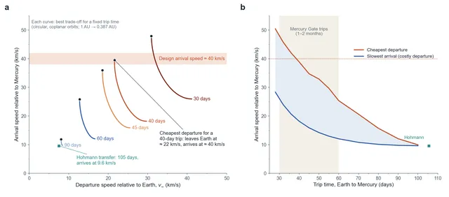
Figure 1. Fast Earth–Mercury transfers. (a) For each trip time, the best trade-off between departure speed from Earth and arrival speed at Mercury; black dots mark the cheapest departure. (b) Arrival speed against trip time for the cheapest departure and for the slowest possible arrival.
Lambert solutions for circular, coplanar orbits at 1 AU and 0.387 AU. Mercury's real orbit is eccentric (e = 0.21), so actual values vary by launch window.
2. Moving the propulsion off the ship
Electromagnetic launch already exists on Earth. A carrier's electromagnetic catapult accelerates an aircraft to take-off speed over roughly 90 m, and a coilgun energises its coils in sequence to push a magnetised projectile along. If the accelerator stays outside the ship, the ship carries no propellant for it. When braking, the same coils can take the ship's kinetic energy back and keep it for the next launch.
The ship needs magnets of its own. In the storyboard the cargo ship is a long cylinder wrapped in hoop after hoop of superconducting coil, which lights up before acceleration or braking begins. These are what the gate coils push against.
3. Braking distance: the physical floor
Whatever the braking method, the deceleration a, the change in speed and the braking distance L are tied together:
Table 2. Braking distance from 40 km/s to 2.97 km/s
| Deceleration | Braking distance | Duration | Suitable for |
|---|---|---|---|
| 5 g | About 16,200 km | 12.6 min | Crew only in extremis |
| 10 g | About 8,100 km | 6.3 min | Beyond sustained human tolerance |
| 100 g | About 810 km | 38 s | Hardened equipment |
| 1,000 g | About 81 km | 3.8 s | Overload-rated containers (raw materials, potted equipment) |
| 10,000 g | About 8 km | 0.4 s | Gun-hardened electronics |
The concept for the film listed 10 g as close to the crewed limit. The distance is right, but the duration matters as much as the peak. Trained, reclining crews have tolerated around 9 g for about a minute and 4–5 g for a few minutes; six minutes at 10 g is far outside that range (Figure 2b). A crewed gate would need about 3 g and a corridor of about 27,000 km.
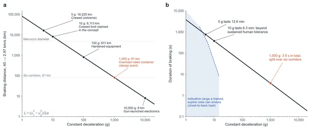
Figure 2. Braking distance and duration. (a) Distance needed to brake from 40 km/s to 2.97 km/s at constant deceleration. (b) Duration of the same braking, with an indicative human-tolerance region for chest-to-back loading.
A thin coil can push on the ship only during the few tens of metres while the ship passes through it. Taking 6 km/s off in 50 m would mean about 450,000 g. So each gate cannot be a single ring. It is an entrance main ring followed by a braking corridor built from a long string of superconducting rings. The storyboard image of fields linking up "so that a tube gradually appears between the rings" is exactly this corridor.
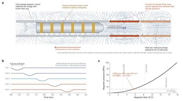
Figure 3. Inside a braking corridor. (a) Computed field lines of the container's superconducting hoops and one opposing corridor coil, section through the axis. (b) The LC timing: each corridor coil carries current for one half-cycle while the container passes. (c) Magnetic pressure against field strength, with the 1,000 g design point.
At 1,000 g the six gates need about 81 km of corridor between them, about 13.5 km each (Section 5 refines this). Raw materials, metal ingots and potted equipment can take this load; people cannot. The Mercury Gate is first of all a freight system, which matches its original task: delivering large amounts of engineering equipment and starter material to Mercury.
4. The field in the corridor
At 1,000 g, a 100 t container needs a force of about 9.8×10⁸ N. The container is about 10 m across, a cross-section of about 78.5 m², so the magnetic pressure and field must be about:
This treats the force as a pressure on the container's cross-section, which is a rough but standard estimate. 5.6 T is comparable to large superconducting magnets in service today: clinical MRI runs at 1.5–3 T, LHC dipoles at 8.3 T. The power is what stands out. The container enters the first gate at 40 km/s and hands over about 1.3×10¹³ J in 0.35 s, a peak power of about 39 TW. In principle superconducting coils can handle this, because the energy moves from the container's motion into the magnetic energy of coil currents without passing through a generator. In practice the hard part is the switching: at 39 TW, a current of one million amperes means a voltage of about 40 MV across the circuits. Insulation and fast switches at that level are the corridor's main engineering problem.
5. Six gates, each taking the same share of the squared speed
If each gate removes the same share of the squared speed, each gate takes the same energy from the container and needs the same corridor length, at least as seen from Mercury.
Table 3. One arrival (100 t container, 1,000 g)
| Gate | Speed change | Energy given up (Mercury frame) | Energy into the coils (gate frame) | Corridor at 1,000 g | Transit time | Impulse on the gate |
|---|---|---|---|---|---|---|
| 1 (high orbit) | 40.0 → 36.5 km/s | 1.33×10¹³ J | 1.30×10¹³ J | 13.2 km | 0.35 s | 3.5×10⁸ kg·m/s |
| 2 (middle orbit) | 36.5 → 32.7 km/s | 1.33×10¹³ J | 1.28×10¹³ J | 13.1 km | 0.39 s | 3.8×10⁸ kg·m/s |
| 3 (low orbit) | 32.7 → 28.4 km/s | 1.33×10¹³ J | 1.26×10¹³ J | 12.8 km | 0.44 s | 4.3×10⁸ kg·m/s |
| 4 (50 km orbit) | 28.4 → 23.2 km/s | 1.33×10¹³ J | 1.17×10¹³ J | 12.0 km | 0.52 s | 5.1×10⁸ kg·m/s |
| 5 (50 km orbit) | 23.2 → 16.6 km/s | 1.33×10¹³ J | 1.13×10¹³ J | 11.5 km | 0.68 s | 6.7×10⁸ kg·m/s |
| 6 (50 km orbit) | 16.6 → 2.97 km/s | 1.33×10¹³ J | 0.92×10¹³ J | 9.4 km | 1.39 s | 1.4×10⁹ kg·m/s |
All values are calculations. Speeds are relative to Mercury.
Together the six gates take about 8×10¹³ J from each container, roughly what the Three Gorges power station generates in an hour at its full 22.5 GW. On leaving the sixth gate the container moves at exactly the circular orbital speed at 50 km altitude and joins that parking orbit.
The gates are not standing still, though. Each one is in orbit, and the part of its orbital velocity along the approach line is moving in the same direction as the container. In the gate's own frame the container is slower, so less energy goes into the coils and the corridor can be shorter:
Here $v_{\parallel}$ is the gate's orbital velocity along the approach line. For gates 4–6 it is the full 2.97 km/s; at the outer gates the approach line cuts their orbits at a steep angle and it is 0.8–1.6 km/s. The rest of the container's energy, about 9×10¹² J per arrival in total, does not disappear. It goes into the gates' orbital energy and is exactly the recoil discussed in Section 7. The practical result is good news for the design: the largest load on any main ring is 1.30×10¹³ J, and no corridor needs to be longer than about 13.2 km.
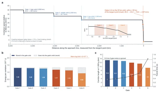
Figure 4. One arrival through the chain. (a) Container speed along the approach line; gates 4–6 sit close to the tangent point (inset). (b) Energy per container at each gate, split into what reaches the coils and what goes into the gate's orbit. (c) Corridor length at 1,000 g and transit time.
6. The geometry of the chain
At 40 km/s, Mercury's gravity bends the container's path only slightly over a few thousand kilometres, so the six gates line up along a nearly straight line. That line touches the 50 km parking orbit. The last gate sits at the point of contact, where its orbital velocity points along the line, so the container leaves it at the same speed as the gate.
Table 4. Gate positions along the approach line
| Gate | Orbit | Altitude | Distance to the tangent point (along the line) | Orbital period |
|---|---|---|---|---|
| 1 | High | About 3,500 km | About 5,390 km | 5.4 h |
| 2 | Middle | About 2,300 km | About 4,030 km | 3.8 h |
| 3 | Low | About 1,300 km | About 2,790 km | 2.7 h |
| 4–6 | Parking orbit | About 50 km | Within about 50 km of the tangent point | 1.5 h |
Calculation, Mercury radius 2,439.7 km.
Two corrections to the "straight line" picture are needed. First, the container takes about 170 s to coast from gate 1 to the tangent point, and over that time Mercury's gravity pulls its path about 14 km away from a straight line. The gates therefore sit on the computed trajectory rather than on a ruler line; this is routine navigation, but at 40 km/s it has to be planned to metres. Second, gates 1–3 cross the approach line at an angle. Their orbital velocity has a component of about 1.8 km/s across the line, so during its 0.35–0.44 s in the corridor the container drifts sideways by 600–800 m relative to the gate. Each outer corridor has to be aimed along the container's velocity relative to the gate, not along the line itself.
The four gate orbits were chosen to fit around the solar rings of the earlier film. The rings lie in the terminator plane, at altitudes of 100–1,200 km, 1,400–2,200 km and 2,400–3,060 km; the gates orbit in the equatorial plane and cross the ring plane twice per orbit. The low and middle orbits pass through the two 200 km gaps between the rings, and the high orbit lies outside them, with at least 60 km of clearance on each side of a ±40 km drift band. A fast arrival from Earth comes in from the night side, moving almost straight toward the Sun, so the approach line crosses the ring plane only near the tangent point.
The innermost ring starts at 100 km, which sets the height of the lowest gates. Gates 4–6 and the parking orbit they feed fly at about 50 km, so their ±40 km drift band (10–90 km) stays at least 10 km below the ring. Mercury has almost no atmosphere, and its highest terrain rises only a few kilometres above the mean surface, so 50 km is a practical orbit. As for lunar orbiters at similar heights, regular small trims are needed to counter gravity anomalies in the crust. The orbital speed at 50 km is 2.97 km/s.
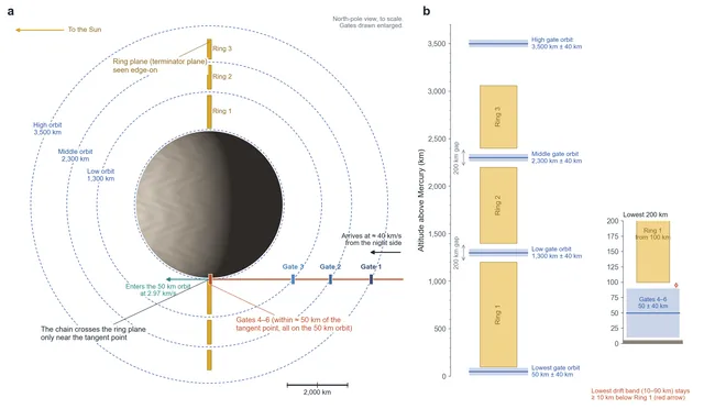
Figure 5. Gate orbits, the approach line and the solar rings. (a) North-pole view to scale: the rings in the terminator plane appear edge-on; the approach line touches the 50 km parking orbit. (b) Altitude ladder of the rings, the 200 km gaps and the gate orbits with their ±40 km drift bands; the zoom shows the clearance between the lowest band and the innermost ring.
Orbits at different heights have different periods, so the six gates line up only at particular moments. A container's arrival time is fixed when it leaves Earth, which leaves one to two weeks to adjust the gates' phases. Shifting a gate on the 50 km orbit by 45° along its orbit in 10 days takes about 1.5 m/s in total (one burn to start the drift, one to stop it); for the high orbit it is about 3.6 m/s. The chain only has to be aligned for the roughly three minutes the container spends inside it. With 24 gates in 4 chains spread around Mercury at different phases, the system offers several windows for arrivals and departures.
7. Recoil and rebalancing
When the container slows down, the gate is pushed forward. The gate structure itself weighs only a few thousand tonnes, and a single impulse would knock it out of its orbit. So each gate carries a counterweight of about a million tonnes of Mercurian rock, a block about 90 m across (setting; at 2,800 kg/m³). A small impulse along the direction of motion of a circular orbit raises the opposite side of the orbit:
Table 5. Effect of one arrival on a gate's orbit (counterweight 10⁹ kg)
| Orbit | Orbital speed | Kick per arrival | Peak height change |
|---|---|---|---|
| 50 km orbit (gates 4–6) | 2.97 km/s | 0.5–1.4 m/s | About 1.7–4.6 km |
| Low | 2.43 km/s | About 0.43 m/s | About 1.9 km |
| Middle | 2.16 km/s | About 0.38 m/s | About 2.0 km |
| High | 1.93 km/s | About 0.35 m/s | About 2.2 km |
Calculation. For gates 1–3 the kick follows the approach line, which crosses their orbits at 47–65°; only part of it lies along the orbit, so the peak change is about half of what the formula above gives for a purely along-orbit kick (4.3, 3.4 and 2.7 km).
Each gate is allowed to wander within a band of about ±40 km in height. Gate 6 takes the largest kick: each arrival raises its mean height by about 2.3 km, so a run of about 17 arrivals in a row would take it to the edge of the band. If every kick happened at the same point of its orbit, the high side of the orbit would rise twice as fast, and the limit would come after about eight. There are three ways to rebalance. Arrivals push the gates up and departures push them down, so two-way traffic cancels itself. The four chains sit at different phases, so jobs that need a gate to be pushed up or down can be routed to the chain that needs it. Whatever is left is trimmed by small thrusters on the gates. This is the same rebalancing logic as in momentum-exchange tether (MXER) concepts.
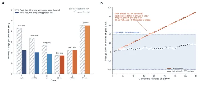
Figure 6. Recoil on the gates. (a) Kick per container and the resulting peak change in orbit height for each gate. (b) Mean altitude of gate 6 for arrivals only and for mixed traffic, against the ±40 km band.
8. Storage: LC resonance and the superconducting main ring
Magnetic energy in a superconducting coil is the most direct way to store the energy, but structural strength limits how much a coil can hold (the virial theorem):
This is a lower bound on structural mass for an ideal design; real magnets need two to three times more. A 1,500 t main ring built from a structural material with the strength of carbon-nanotube fibre (20 GPa at 1,500 kg/m³, a setting value well beyond today's bulk fibres) could hold at most about 2×10¹³ J, enough for the 1.30×10¹³ J the busiest gate receives from one container. This is what "the largest single superconducting coil humans have ever built" means in engineering terms: it is the gate's battery.
Each ring in the corridor forms an LC resonant circuit with a capacitor bank. At 40 km/s a container passes a 30 m coil in about 0.75 ms; at 3 km/s it takes about 10 ms. Each circuit swings its current over one half-cycle in step with the container, so the container's coils always feel a force pushing backwards, and its kinetic energy flows step by step into the main ring. A 13 km corridor holds about 450 such coils. Departures run the same process in reverse. Between two arrivals the main ring either hands its energy to a departing container or sends it to the base on Mercury through the power network.
9. Active braking, not eddy currents
Table 6. Two ways to brake
| Method | Principle | Where the energy goes | Verdict |
|---|---|---|---|
| Passive (eddy or induced currents) | The container passes through conductors; induced currents produce drag | All of it becomes heat: 1.3×10¹³ J vaporises roughly 1,700–2,200 t of iron or copper | Not feasible |
| Active (superconducting currents) | Gate and container coils repel each other in timed sequence | Stored in the main ring for the next launch | Adopted |
Lenz's law still has a job to do here, but a different one: guidance.
10. Negative feedback: a built-in course corrector
The container's superconducting coils resist any change in the magnetic flux through them. If the container drifts toward one side of the main ring, the flux change on that side is stronger, so is the repulsive force, and the container is pushed back toward the centre. This is natural negative feedback, the same principle as the null-flux guidance of superconducting maglev trains.
It has limits. The restoring force acts only within the bore of the ring, so it can correct errors of metres, not kilometres. Errors that build up over tens of millions of kilometres of flight have to be removed by the container's own terminal guidance before it reaches gate 1. The main ring then keeps it centred, including against the sideways drift at the outer gates described in Section 6.
11. On the ground: a 50 km braking tunnel
A container in the 50 km parking orbit can be handed on by an orbital transfer station, or it can land directly. The braking tunnel on the ground is 50 km long and brings it from orbital speed to rest:
9 g for about 34 seconds is close to the limit of what a reinforced crew capsule with trained, reclining occupants could take, and easily within a cargo container's rating. In the film the tunnel mouth is about 500 m across and narrows underground to 100 m, ending at a docking track. The film shows the mouth at about 30° to the ground. A container dropping from the 50 km orbit with a small burn of about 15 m/s actually reaches the surface almost horizontally at about 3.0 km/s, close to the speed used above. A 30° entry would first need about 2.0 km/s of braking in orbit. The natural mouth is therefore a long, shallow trench that steepens only once the container is inside.
12. Main failure modes
Table 7. Failures and responses
| Failure | Trigger | Consequence | Design response |
|---|---|---|---|
| Chain misaligned | Phase error | Container misses a gate | Phases locked 10 days before arrival; backup chain |
| Main ring full | Arrivals too closely spaced | Gate cannot absorb more energy | Send energy out; queue arrivals |
| Quench | Local heating or debris impact | Corridor loses power | Segmented corridor; no-insulation coils |
| Container out of control | Coil failure | High-speed object leaves the chain | Chains aimed away from Mercury's surface and other orbits |
| Gate leaves its band | Too much one-way traffic | Gate drifts out of its altitude band | Route jobs to other chains; thruster trim |
| Collision with the rings | Lowest gates drifting up | Gates 4–6 reach the innermost ring at 100 km | Lowest gates fly at about 50 km; drift band held to 10–90 km |
13. A metro for the Solar System
Run backwards, the same chain is an accelerator. A container leaves the 50 km parking orbit, passes the six gates in reverse order and is sent off at 40 km/s anywhere in the Solar System. Each gate is pushed backwards, which lowers its orbit and cancels the rise from an arrival. Similar chains are built in low Earth orbit and around Mars, and together with rotating skyhooks and space elevators they become the infrastructure of the Solar System. The trip between Earth and Mercury drops from seven years to one or two months. The star gates that follow scale the same idea to the asteroid belt.
References and calculation basis
- NASA NSSDC, Mercury Fact Sheet: radius 2,439.7 km, GM = 2.2032×10¹³ m³/s², semi-major axis 0.387 AU.
- NASA, MESSENGER mission (launch August 2004, orbit insertion March 2011) and ESA, BepiColombo mission (launch October 2018, arrival scheduled for late 2026): gravity-assist cruise times.
- Hoyt and Forward, Momentum-Exchange/Electrodynamic-Reboost (MXER) Tether: momentum exchange and orbit rebalancing.
- Moon (1982), The virial theorem and scaling laws for superconducting magnet systems: the structural lower bound on superconducting energy storage.
- US Navy EMALS and coilgun literature: electromagnetic launch.
- NASA-STD-3001 and centrifuge studies of sustained acceleration tolerance: human limits for chest-to-back loading.
- Scienshell, Mercury solar rings: ring altitudes and the terminator-plane geometry.
- Calculation basis: g₀ = 9.80665 m/s²; container 100 t; 1,000 g; structural specific strength 1.33×10⁷ J/kg; counterweight 10⁹ kg (setting); Sun GM = 1.32712×10²⁰ m³/s²; Earth and Mercury on circular coplanar orbits for the transfer estimates. Gates are treated as point masses on circular equatorial orbits; braking in each corridor is taken as impulsive for the trajectory and as constant 1,000 g for the corridor lengths.