
Jupiter Magnetic Spacecraft
A quantitative design study of lift, circuit closure, mass, rotation, energy, radiation, lightning, and quench risk
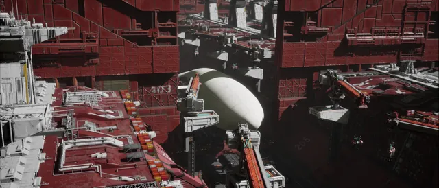
Concept imagery.
Gravity at Jupiter's 1 bar level is 24.79 m/s², more than 2.5 times Earth's. Reaching a low orbit from there requires another 29.5 km/s of speed, demanding a mass ratio of roughly 800:1 from a chemical rocket. This fictional setting begins with a question: since Jupiter has the strongest planetary magnetic field in the Solar System, could a spacecraft use that field to climb and descend?
The concept is simple: wrap the hull in superconducting conductors, drive a current through them, and let the Lorentz force support an entire city. Turning that sketch into a spacecraft requires a quantitative account. We begin with force and circuit closure, then work through mass, energy, radiation, lightning, and structure, before setting out how each assumption could be tested.
The calculations below are order-of-magnitude estimates, not engineering predictions. Every key number is identified as a measurement, an assumption, or a calculation. The properties assigned to metastable metallic hydrogen belong to the fictional setting; they are not established facts. They are discussed separately below.
The main findings
The lift calculation works on its own. A total of 8.4 million conductors, each 12 km long and carrying 10,000 A in a 4.2 G field, produces 4.23×10¹¹ N of force, enough to support a total mass of 17.08 million tonnes.
The hardest obstacle is a conservation law. A closed circuit experiences no net force in a uniform magnetic field. Superconducting shielding cannot evade this constraint. The article therefore states the necessary departure from known physics explicitly as fictional postulate P1 in Section 4, and calculates the scales permitted by known physics without it.
Jupiter's rotation provides the largest benefit. When the spacecraft corotates with Jupiter, the peak current falls from 263,000 A to 10,575 A. There is also no need to plan for hovering all the way to 1.88 million km: release the spacecraft at roughly 180,000 km and it can coast toward Io.
Three budgets constrain the design: the mass of the return conductors, the 118 MPa magnetic pressure between the conductor layers, and the waste heat generated during ascent. The original parameters need modest adjustments to balance these budgets, while retaining 8.4 million conductors, 10,000 A, 12 km, and 17 T.
Table 1. Design baseline
| Parameter | Value | Basis |
|---|---|---|
| City payload | 10 million tonnes | Assumption |
| Hull | Cylinder, axis east–west, L = 12 km, R ≈ 977 m | Assumption; radius inferred from 17.19 T |
| Number of circuits × current per conductor | 8.4 million × 10,000 A; total current 8.4×10¹⁰ A | Assumption |
| Lift-conductor cross section | 0.1 cm², reduced from 1 cm²; J = 10⁵ A/cm² | Revised after calculation; see Section 5 |
| Metallic-hydrogen density / critical temperature | 700 kg/m³ / 300 K | Assumptions; not experimentally established |
| Jupiter's equatorial magnetic field at 1 bar | 4.2 G | Measurement, rounded |
| Gravity at 1 bar | 24.79 m/s², from GM/r², excluding rotation | Measurement |
| Total lift / supported total mass | 4.23×10¹¹ N / 17.08 million tonnes | Calculation |
| Gap between conductor layers | 2 m; the 10 m separation between inner and outer hulls is retained | Revised after calculation; see Section 12 |
| Gap field / magnetic pressure / magnetic energy | 17.2 T / 118 MPa / 1.73×10¹⁶ J | Calculation |
| Electrical power for ascent / ascent time | 1 TW / approximately 131 days | Assumption / calculation |
1. The gravity-well budget: rockets are possible, but costly
First, establish why this problem warrants a different approach. At Jupiter's equatorial 1 bar level, circular orbital speed is approximately 42.1 km/s. Atmospheric rotation already provides 12.6 km/s, leaving a shortfall of about 29.5 km/s. Substituting into the Tsiolkovsky rocket equation:
Table 2. Mass ratios for reaching orbit, with Δv = 29.5 km/s and no allowance for gravity or aerodynamic losses
| Propulsion | Specific impulse $I_{sp}$ | $m_{0}$/$m_{f}$ | Basis |
|---|---|---|---|
| Hydrogen–oxygen chemical rocket | 450 s | Approximately 804 | Typical specific impulse |
| Metallic-hydrogen recombination | 1,700 s | Approximately 5.9 | Theoretical upper limit from Silvera & Cole |
| High-specific-impulse fusion, illustrative | 5,000 s | Approximately 1.8 | Assumption |
| High-specific-impulse fusion, illustrative | 30,000 s | Approximately 1.1 | Assumption; simultaneously providing acceleration above 2.5 g is difficult |
The table does not support the claim that rockets are impossible. A metallic-hydrogen rocket has a mass ratio of only 5.9. But a spacecraft with a final mass of 17.08 million tonnes would burn about 83 million tonnes of propellant on each ascent to orbit, releasing approximately 1.8×10¹⁹ J. That is the same order of magnitude as the 1.1×10¹⁹ J required for magnetic ascent below. Magnetic propulsion saves propellant rather than energy: it replaces the need for reaction mass with a need for electrical power, while allowing the spacecraft to stop at any altitude and recover potential energy on descent.
2. Choose a planet by B/g, not B alone
The current–length product needed to support a mass M is:
The relevant measure of a planet's suitability for magnetic levitation is therefore B/g. Table 3 retains a magnetic-field index normalized to 10,000 for Jupiter and adds this correction.
Table 3. Magnetic-levitation conditions on bodies with intrinsic magnetic fields
| Body | Surface field (G) | Field index | g (m/s²) | B/g relative to Jupiter | Notes |
|---|---|---|---|---|---|
| Jupiter | 4.17 | 10,000 | 24.79 | 1 | Dipole-dominated; strongest field |
| Earth | 0.50 | 1,199 | 9.81 | 0.30 | Approximate global-average scale; about 0.31 G at the equator |
| Uranus | 0.23 | 552 | 8.87 | 0.15 | Magnetic axis tilted about 60° from the rotation axis; complex field |
| Saturn | 0.21 | 504 | 10.44 | 0.12 | Very regular but relatively weak dipole |
| Neptune | 0.14 | 336 | 11.15 | 0.075 | Strong multipole components |
| Ganymede | 0.0075 | 18 | 1.43 | 0.031 | The only moon with an intrinsic magnetic field |
| Mercury | 0.003 | 7 | 3.70 | 0.0048 | Extremely weak field |
| Mars, Venus | ≈0 | 0 | — | 0 | No global intrinsic magnetic field |
Jupiter still ranks first, but its advantage over Earth is a factor of 3.3 rather than the factor of 8 suggested by field strength alone. This does not weaken the case: the planet with the deepest gravity well also has the strongest magnetic field per unit gravity. The place that most needs this technology is also where it works best.
3. Lift comes from current elements
A conductor of length L carrying current I perpendicular to a magnetic field experiences a force:
The direction must also be checked. Jupiter's dipole has the opposite polarity to Earth's, so the field at its equator points south. A current flowing from east to west therefore experiences an upward force. This part of the concept is correct; the same arrangement on Earth would experience a downward force.
Whether a conductor can support its own weight depends on a single dimensionless ratio:
Here J is current density and ρ is conductor density. At ρ = 700 kg/m³, J = 10⁴ A/cm² gives a ratio of 2.42, while J = 10⁵ A/cm² gives 24.2. The first value appears generous, but the return conductors in Section 5 will consume that margin.
The material assumption. High-performance YBCO tapes have a $J_{c}$ of roughly 10⁶–10⁷ A/cm². This setting assumes that metastable metallic hydrogen can reach 10⁸–10⁹ A/cm² at a density of 600–800 kg/m³: lighter than water and about one-thirteenth the density of copper, at 8,960 kg/m³. It would not be the lightest metal; lithium has a density of just 534 kg/m³. The proposed advantage is the combination of low density and superconductivity. The distinction from experimental evidence is essential: Loubeyre and colleagues reported a metallic state near 425 GPa that reverted upon decompression, and a 2022 experimental preprint did not observe a metastable state at zero pressure. The properties used here are fictional assumptions, not an extrapolation of those results.
4. The circuit must close: the hardest constraint
Current must return to its starting point. If the return conductor is exposed to Jupiter's magnetic field, its force acts downward and cancels the lift. An intuitive solution is to hide the return conductor inside a superconducting shield: the Meissner effect excludes Jupiter's field, so the return conductor sees no field and experiences no opposing force.
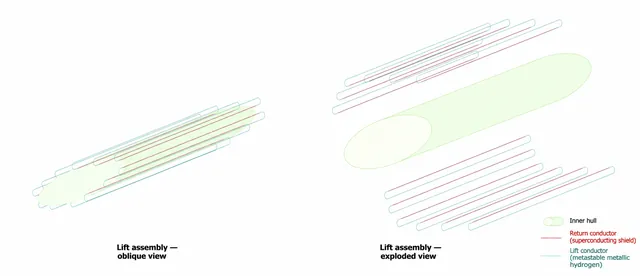
Figure 1. Oblique and exploded views of the lift assembly. Teal indicates lift conductors, red the superconductively shielded return conductors, and green the inner hull.
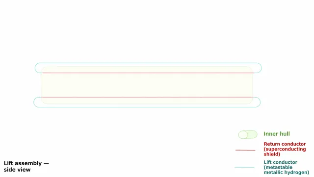
Figure 2. Side view of the lift assembly. The lift conductors turn around at both ends and return through the inner layer.
This solution encounters a constraint more fundamental than material strength. Any localized, steady current distribution, including the induced currents in the shield, satisfies ∇·J = 0. In a uniform external field:
Shielding transfers the reaction force from the conductor to the outer wall of the shield. The surface currents that exclude the external field experience precisely the force that would otherwise act on the return conductor. The net force on the whole spacecraft remains zero.
Energy gives the same answer. When the entire circuit undergoes a rigid translation, the magnetic flux through it remains unchanged. The induced electromotive force is therefore zero and the power supply does no work. If a net lift force nevertheless raised the spacecraft, gravitational potential energy would appear from nowhere.
In classical electrodynamics, the net force available to a closed current system is a gradient force:
Jupiter's magnetic-field gradient is very shallow. Supporting 17.08 million tonnes would require a magnetic moment of 2.4×10²² A·m². Size and stress must be considered together: the stored magnetic energy cannot exceed what the structural material can contain, as expressed by the virial theorem.
Here a is coil radius, m is magnetic moment, and κ ≈ 3 is an inductance coefficient. We assume σ/ρ = 10⁷ J/kg, a carbon-nanotube-level value. Table 4 gives the results. Every kilogram is allocated to structure, leaving nothing for payload, so these are optimistic lower bounds.
Table 4. Gradient-force designs permitted by known physics, with σ/ρ = 10⁷ J/kg
| Total mass | Required magnetic moment (A·m²) | Minimum loop radius a | Loop current (A) |
|---|---|---|---|
| 17 million tonnes, city scale | 2.4×10²² | Approximately 8,600 km | 1.0×10⁸ |
| 10,000 tonnes | 1.4×10¹⁹ | Approximately 720 km | 8.6×10⁶ |
| 100 tonnes | 1.4×10¹⁷ | Approximately 160 km | 1.9×10⁶ |
| 1 tonne | 1.4×10¹⁵ | Approximately 34 km | 4.0×10⁵ |
Forcing the city-scale magnetic moment into a 12 km structure requires a loop current of 2.1×10¹⁴ A, a central field of 2.2×10⁴ T, and stored energy of 5.1×10²⁶ J: one-third of the spacecraft's rest-mass energy. An upward gradient force also requires the magnetic moment to be antiparallel to the external field, an unstable orientation that demands continuous active control.
Table 5. Circuit-closure approaches for a total mass of 17.08 million tonnes
| Approach | Where momentum is transferred | Requirements | Assessment |
|---|---|---|---|
| A. Shielded return | No recipient under classical physics | Net force is zero unless new physics is introduced | Explicitly adopted as fictional postulate P1 |
| B. Dipole gradient force | Jupiter's magnetic-field gradient | Loop radius of about 8,600 km; antiparallel magnetic moment; active attitude control | Physically allowed, but no longer a 12 km spacecraft |
| C. Closure through ambient plasma | Ionosphere and magnetosphere | Return current of 8.4×10¹⁰ A through surrounding plasma; insufficient charge carriers at 1 bar | Ruled out at city scale; viable at probe scale |
Approach C has a natural reference. The current system linking Io and Jupiter carries roughly 1 MA to 3 MA. Put that current through a 12 km conductor in a 4.2 G field and it supports only about 200–600 tonnes, while requiring operation above the ionosphere. It suits a pathfinder, but cannot support a city.
Fictional postulate P1: the premise for all subsequent calculations
A metastable metallic-hydrogen shield can couple the reaction force on the return segment to Jupiter's magnetic field, making the complete circuit equivalent to an open lift-current element. The associated induced electromotive force is ε = BLv, ensuring that electrical power equals Fv and that energy remains conserved.
This is the setting's sole assumption beyond known electrodynamics. It must be stated as a fictional premise, not presented as a derived result. A tabletop experiment could directly falsify it, as discussed in Section 15.
5. Return conductors have mass: the budget must close again
Under P1, only the outer layer produces lift, but the return conductors and shields must also be supported. Let the total circuit mass be k times the mass of the lift conductor. When the lift conductor, return conductor, and shield each contribute one equal share, k = 3; the shield wall thickness is discussed below.
Table 6. Conductor cross-section tradeoffs for a 10-million-tonne payload, with I = 10,000 A
| Cross section | J (A/cm²) | Mass of one lift conductor | k | Net force per circuit | Circuits required | Total conductor mass |
|---|---|---|---|---|---|---|
| 1 cm², lift conductor only | 10⁴ | 840 kg | 1 | 29,576 N | 8.38 million | 7.04 million tonnes |
| 1 cm², including return conductor | 10⁴ | 840 kg | 2 | 8,753 N | 28.3 million | 47.5 million tonnes |
| 1 cm², including shield | 10⁴ | 840 kg | 3 | −12,071 N | No solution | No solution |
| 0.5 cm² | 2×10⁴ | 420 kg | 3 | 19,200 N | 12.9 million | 16.3 million tonnes |
| 0.2 cm² | 5×10⁴ | 168 kg | 3 | 37,900 N | 6.54 million | 3.30 million tonnes |
| 0.1 cm² | 10⁵ | 84 kg | 3 | 44,200 N | 5.61 million | 1.41 million tonnes |
| 0.01 cm² | 10⁶ | 8.4 kg | 3 | 49,800 N | 4.98 million | 125,000 tonnes |
A 1 cm² conductor cannot support its complete circuit. The 840 kg figure accounts for the lift conductor alone. Add the return conductor and shield, and net force becomes negative. Reducing the cross section resolves this within the assumed current-density margin. At 0.1 cm², the design current density remains three to four orders of magnitude below the assumed $J_{c}$, and the required number of circuits falls to 5.61 million.
This design nevertheless retains 8.4 million circuits. The additional roughly 2.8 million support the tie-rod structure, cooling system, and propulsion equipment; Section 12 provides the full mass budget. A shield with an annular cross section of 0.1 cm² and a radius of 5 mm has a wall thickness of approximately 0.3 mm. The three conductor layers have a combined cross-sectional area of 252 m², occupying 0.41% of the space between the hulls and 0.0084% of the spacecraft's total cross section.
6. Ascent: Jupiter's rotation does half the work for you
The current for stationary hovering keeps rising
Ignoring rotation, the equilibrium condition is ILB(r) = Mg(r). Gravity falls as r⁻², while a dipole magnetic field falls as r⁻³, so:
Following this line out to Callisto's orbit (1.88 million km) would require the current to rise to 263,000 A. The material would still have enough current-carrying capacity, but this calculation hides an unstated action: the spacecraft has stopped rotating with Jupiter.
Co-rotation is the natural starting point
When the spacecraft leaves the atmosphere, it already has a rotational speed of 12.6 km/s. The magnetic field rotates with the same 9.925-hour period, so it is stationary in the co-rotating frame. The centrifugal term must therefore be subtracted from the effective load:
Both the current peak and the zero-current point have analytical solutions:
Table 7. Lift requirements during an equatorial ascent ($I_{0}$ = 10,000 A corresponds to 24.79 m/s²)
| r (km) | Location | g | ω²r | a | B (G) | Stationary-hovering I (A) | Co-rotating I (A) |
|---|---|---|---|---|---|---|---|
| 71,492 | 1 bar cloud tops | 24.79 | 2.21 | 22.58 | 4.20 | 10,000 | 9,108 |
| 80,000 | Intense radiation region | 19.80 | 2.47 | 17.33 | 3.00 | 11,190 | 9,792 |
| 90,000 | Near the inner edge of the halo ring | 15.64 | 2.78 | 12.86 | 2.11 | 12,589 | 10,349 |
| 100,800 | Peak current | 12.47 | 3.12 | 9.35 | 1.50 | 14,099 | 10,575 |
| 110,000 | Halo ring | 10.47 | 3.40 | 7.07 | 1.15 | 15,386 | 10,387 |
| 120,000 | Inside the main ring | 8.80 | 3.71 | 5.09 | 0.89 | 16,785 | 9,705 |
| 140,000 | Outside the main ring | 6.46 | 4.33 | 2.13 | 0.56 | 19,583 | 6,466 |
| 160,010 | Synchronous orbit | 4.95 | 4.95 | 0 | 0.37 | 22,380 | 0 |
| 180,000 | Near Amalthea | 3.91 | 5.57 | −1.66 | 0.26 | 25,178 | −10,665 |
Accelerations are in m/s². For comparison, stationary hovering would require 58,986 A at Io's orbit (422,000 km), 149,723 A at Ganymede's orbit (1.07 million km), and 263,344 A at Callisto's orbit (1.88 million km).
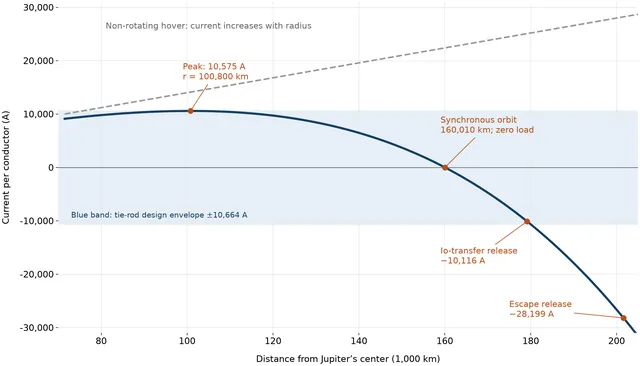
Figure 3. Lift current for the two ascent modes. During co-rotation, the peak is only about 16% above the starting value; beyond synchronous orbit, the load reverses direction.
The peak current falls to about 1/25 of the previous value. Throughout the ascent, the current varies only within ±10,700 A. This also revises the picture of “using magnetic levitation all the way to 1.88 million km”: a co-rotating spacecraft no longer needs to be supported once it reaches 160,000 km.
Beyond synchronous orbit, the spacecraft needs to be held down
Outside synchronous orbit, centrifugal force exceeds gravity, and the spacecraft tends to swing outward. Reversing the current turns the magnetic force into a downward “tether.” Release that tether, and the spacecraft enters a transfer orbit with its local tangential velocity—the same release principle used by a space elevator.
Table 8. Release points and destinations
| Destination | Ideal release radius (km) | Current at release (A) | Sandwich-gap magnetic pressure (MPa) | Additional Δv for release at 180,000 km | Orbital-insertion Δv on arrival |
|---|---|---|---|---|---|
| Io's orbit | 179,160 | −10,116 | 120 | 0 (reached naturally) | 3.95 km/s |
| Europa's orbit | 185,830 | −14,719 | 255 | 1.66 km/s | 4.69 km/s |
| Ganymede's orbit | 190,870 | −18,618 | 408 | 3.06 km/s | 4.89 km/s |
| Callisto's orbit | 195,080 | −22,163 | 578 | 4.19 km/s | 4.65 km/s |
| Escape from Jupiter | 201,600 | −28,199 | 936 | 5.87 km/s | — |
Magnetic pressure rises with the square of the current, so a higher release point is not necessarily better. This study uses 180,000 km as the normal release radius: the tie rods are designed for 134 MPa, and the spacecraft naturally coasts out to about 440,000 km, just beyond Io's orbit. For more distant moons, the propulsion system supplies the additional Δv shown in the table; the orbital-insertion Δv does not include gravity assists from the moons. This route also crosses the main ring (roughly 123,000–129,000 km) and the orbits of Metis and Adrastea. The main ring is very tenuous, but the corridor must avoid the small moons.
The energy budget
In the co-rotating frame, the power supply only has to cover the change in effective potential:
Table 9. Ascent energy (total mass: 17.08 million tonnes)
| Mode | Specific energy (J/kg) | Total energy (J) | Electricity (kWh) | Years of Three Gorges generation | Days of global electricity consumption |
|---|---|---|---|---|---|
| Stationary hovering to 120,000 km | 7.16×10⁸ | 1.22×10¹⁹ | 3.40×10¹² | 34 years | 40 days |
| Stationary hovering to 1.88 million km | 1.70×10⁹ | 2.91×10¹⁹ | 8.09×10¹² | 81 years | 95 days |
| Co-rotation to 120,000 km | 5.73×10⁸ | 9.79×10¹⁸ | 2.72×10¹² | 27 years | 32 days |
| Co-rotation to synchronous orbit | 6.63×10⁸ | 1.13×10¹⁹ | 3.15×10¹² | 32 years | 37 days |
The comparisons assume roughly 100 billion kWh per year for Three Gorges and about 85 billion kWh per day for global electricity consumption; both are rounded assumptions. The total mass in the table includes the conductors and structure, so the values are 71% higher than for the 10-million-tonne city alone.
If the spacecraft starts in co-rotation and continues all the way to escape, its total energy must increase by 1.69×10⁹ J/kg, while the power supply contributes only about 6×10⁸ J/kg. The remaining roughly two-thirds comes from Jupiter's rotation: under P1, the magnetic field transfers the reaction force to Jupiter, and the spacecraft borrows the planet's angular momentum through that field. For Jupiter, this energy transfer is entirely negligible.
Power determines the duration; waste heat sets the upper limit on power. Assume 40% generating efficiency, radiators operating at 1,000 K, and an emissivity of 0.9:
Table 10. Electrical power, ascent time, and radiator area
| Electrical power | Ascent time | Initial ascent speed | Waste heat | Radiator area at 1,000 K | Fraction of hull area |
|---|---|---|---|---|---|
| 100 GW | About 3.6 years | 0.26 m/s | 150 GW | 2.9×10⁶ m² | 4% |
| 1 TW | 131 days | 2.6 m/s | 1.5 TW | 2.9×10⁷ m² | 40% |
| 10 TW | 13 days | 26 m/s | 15 TW | 2.9×10⁸ m² | 400% |
This study uses 1 TW. At 10 TW, the radiators are already larger than the spacecraft, and the 1,000 K radiators must be reliably thermally isolated from the 300 K conductors. For D–³He fusion, one ascent consumes about 48 tonnes of ³He. This is consistent with the helium-3 article's conversion of 1 tonne per year to 18.7 GW, putting the spacecraft and its fuel network on the same balance sheet. Potential energy can be recovered during descent, but the recovered electricity still needs somewhere to go: storage, radiators, or aerodynamic braking within the atmosphere.
Angular momentum does not arrive automatically. As the spacecraft moves radially, it must gradually accelerate to the local co-rotation speed. Vertically arranged currents can provide an east–west force, and only a small fraction of the main lift is needed: at an ascent speed of 100 m/s, the Coriolis acceleration 2ωv = 0.035 m/s² is about 0.16% of the load at 1 bar.
7. Holding altitude: the magnetic spring is stiff, but undamped
A superconducting loop has zero resistance, so the total magnetic flux linkage through it is conserved. When the city falls, the electromotive force increases the loop current and the lift; when the city rises, the reverse happens. This qualitative assessment is correct. What remains to be calculated is the stiffness of that spring. Take the equivalent inductance of one loop as the flux linkage in the sandwich gap divided by the current:
Table 11. Response of the magnetic spring
| Disturbance | Equivalent force | Fraction of lift | Equilibrium-altitude shift |
|---|---|---|---|
| 1% change in payload | 4.2×10⁹ N | 1% | 819 m |
| 10 m/s vertical airflow | 2.0×10⁸ N | 0.05% | 38 m |
| 50 m/s vertical airflow | 4.9×10⁹ N | 1.2% | 952 m |
| 100 m/s vertical airflow | 2.0×10¹⁰ N | 4.7% | 3.8 km |
The airflow estimates use an atmospheric density of 0.168 kg/m³ at 1 bar, a planform area of 2.34×10⁷ m², and a drag coefficient of 1. The contribution from the loop's magnetic-field geometry is only about 1/290 of the current effect and can be neglected.
A spring does not guarantee stability. A resistance-free loop has no intrinsic damping: once disturbed, the city would keep oscillating with a period of about 6 minutes. In the atmosphere, aerodynamic drag can supply some damping; in vacuum, flux pumps must actively regulate the current. Data from the Galileo probe show atmospheric gravity waves near 6–16 bar, so the active-control system must avoid frequency bands that would resonate with them.
8. Magnetic force has only two directions: corridors and maneuvering
The Lorentz force is always perpendicular to B. This constraint determines where the spacecraft can travel and what additional propulsion it needs.
Magnetic force can counter only the component of gravity perpendicular to B. In a dipole field, the component of gravity along the field lines at magnetic latitude λ is:
Table 12. Effect of magnetic latitude on lift (r = 71,492 km)
| Magnetic latitude λ | |B| / $B_{eq}$ | Fraction of gravity along field lines | Nonmagnetic acceleration required (m/s²) | Lift-current ratio |
|---|---|---|---|---|
| 0° | 1.00 | 0 | 0 | 1.00 |
| 1° | 1.00 | 3.5% | 0.87 | 1.00 |
| 5° | 1.01 | 17% | 4.3 | 0.97 |
| 10° | 1.04 | 33% | 8.2 | 0.90 |
| 30° | 1.32 | 76% | 18.7 | 0.50 |
| 90° (magnetic pole) | 2.00 | 100% | 24.8 | — |
This table changes what “a stronger field near the poles” means. Near the magnetic poles, the field is almost vertical; however strong it is, it cannot provide lift. The spacecraft can ascend and descend only along the magnetic equator, where its equilibrium is unstable in the north–south direction: as it slides away from the equator along the field lines, the component of gravity keeps pulling it farther away, with a characteristic timescale of about 20 minutes (√(r₀/2g)). The spacecraft therefore needs a continuously operating north–south propulsion system.
Jupiter's magnetic axis is tilted by about 10° relative to its rotation axis, so the magnetic and rotational equators intersect near only two longitudes. The ideal ascent and descent corridors for a co-rotating spacecraft lie near those two intersections. At low altitudes, the field is not an ideal dipole—the JRM33 model reveals extensive higher-order structure—so the precise corridor locations must be determined from measured fields.
Table 13. Control in the three directions
| Direction | Can magnetic force be used? | Implementation |
|---|---|---|
| Up–down | Yes | East–west current × north–south magnetic field: the main lift system |
| East–west | Yes | Vertical current × north–south magnetic field; requires additional vertical conductor segments |
| North–south | No | Force cannot act along B; thrusters or aerodynamic forces are needed, including for equatorial stability |
9. Diving: temperature limits the depth, not current
During a descent into the atmosphere, the change in altitude is small compared with Jupiter's radius, so the required current is nearly unchanged. The limiting factor comes from elsewhere: metallic hydrogen's assumed critical temperature of 300 K.
Table 14. Descent profile (Δz relative to 1 bar)
| Pressure | Δz (km) | T (K / °C) | B (G) | I (A) | $J_{c}$ factor | Gas density (kg/m³) | Environment |
|---|---|---|---|---|---|---|---|
| 1 bar | 0 | 165 / −108 | 4.200 | 10,000 | 0.30 | 0.17 | Near the ammonia clouds |
| 5 bar | −61 | 272 / −1 | 4.211 | 9,991 | 0.029 | 0.51 | Water-cloud layer; normal operating depth limit |
| 6 bar | −68 | 289 / 16 | 4.212 | 9,990 | 0.007 | 0.57 | Hard depth limit; lightning-cloud layer |
| 10 bar | −86 | 340 / 67 | 4.215 | 9,988 | 0 | 0.81 | Above the critical temperature |
| 15 bar | −110 | 386 / 113 | 4.219 | 9,985 | 0 | 1.08 | Active refrigeration required |
| 20 bar | −127 | 416 / 143 | 4.222 | 9,982 | 0 | 1.33 | Active refrigeration required |
The temperature–pressure values are based on the Galileo probe's measurements: −133 km and 429 K at 22 bar. Intermediate values are interpolated along an adiabat (T ∝ p⁰·³²), with a mean atmospheric molecular mass of 2.3 g/mol. The probe entered the edge of a 5 μm hot spot; profiles in other regions will differ.
The $J_{c}$ factor is estimated as (1 − T/$T_{c}$)¹·⁵, an assumption. At 6 bar, $J_{c}$ falls to about 0.7%, corresponding to roughly 7×10⁵–7×10⁶ A/cm², still above the design value of 10⁵ A/cm². But the temperature margin there is only 11 K, and interpolation puts the temperature above 300 K at about 7 bar. This makes 5 bar the normal operating depth limit and 6 bar a hard boundary that must not be crossed. Going deeper requires active refrigeration.
Gas buoyancy matters much more than the change in gravity. A hull volume of 3.6×10¹⁰ m³ displaces 6.03 million tonnes of gas at 1 bar and 18.3 million tonnes at 5 bar. If the hull is sealed and its internal gas is lighter than the surroundings, the spacecraft becomes buoyant on its own at about 4.5 bar and would resist sinking farther. A deep dive therefore requires admitting ambient gas into the compartments. In this regime, the magnetic-levitation and aerostat-city concepts can complement one another.
10. Radiation protection: the magnetic shield is in the sandwich gap, not outside the ship
Jupiter's radiation consists mainly of energetic charged particles trapped by its magnetic field. The Galileo probe accumulated more than three times its design radiation dose, making radiation the second major obstacle to entering and leaving Jupiter. Charged particles are deflected by the Lorentz force, so the spacecraft's conductor system also acts as a magnetic shield. The location of that shield, however, is determined by Ampère's circuital law:
Table 15. Net current enclosed by an Amperian loop
| Region | Enclosed net current | Self-generated magnetic field |
|---|---|---|
| Interior (r < 975 m) | 0 | ≈ 0 |
| Coil sandwich gap (975 m < r < 977 m) | 8.4×10¹⁰ A | 17.2 T |
| Outside the ship (r > 977 m) | 0 (lift and return currents cancel) | ≈ 0 |
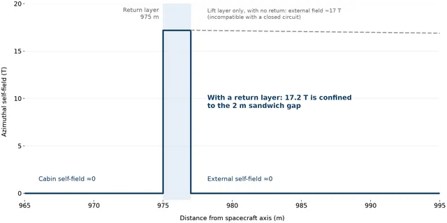
Figure 4. Self-generated magnetic field near the hull. The return layer cancels the external field, confining the full 17.2 T to the sandwich gap.
The picture of a 17 T external field applies only if the lift layer has no return current, which contradicts the requirement for a closed circuit. The correct picture is actually better: after passing through the thin outer skin, particles enter the 2 m thick, strongly magnetized sandwich gap, turn through a semicircle, and are sent back outside.
The criterion is the ratio of gyroradius to sandwich-gap thickness. A normally incident particle is turned back if its gyroradius is smaller than the gap thickness, giving the cutoff momentum:
Table 16. Gyroradii in a 17.2 T field (sandwich gap: 2 m)
| Particle | Kinetic energy | Momentum (MeV/c) | $r_{L}$ | $r_{L}$ / Δ |
|---|---|---|---|---|
| Electron | 1 MeV | 1.42 | 0.28 mm | 0.014% |
| Electron | 10 MeV | 10.5 | 2.0 mm | 0.10% |
| Electron | 100 MeV | 101 | 2.0 cm | 1.0% |
| Proton | 10 MeV | 137 | 2.7 cm | 1.3% |
| Proton | 100 MeV | 445 | 8.6 cm | 4.3% |
| Proton | 400 MeV | 954 | 18.5 cm | 9.3% |
| Sulfur ion (Z = 16, fully ionized) | 320 MeV | 4,380 | 5.3 cm | 2.7% |
All the particles in the table are well below the cutoff momentum, so a 2 m gap is sufficient. Reducing the gap from 10 m to 2 m does not impair protection, but saves a great deal of structure (Section 12).
Three weaknesses in this magnetic shield
- The outer skin still takes hits. Particles must pass through it first, and electrons produce bremsstrahlung there. The response is to use a thin skin made from low-atomic-number material, minimizing particle energy loss; the mass of the inner hull stops the resulting X-rays. The ship's average areal density is about 13.6 g/cm², spreading the city's total mass over the sidewall. This exceeds the order of magnitude of Juno's titanium radiation vault, but determining the actual dose requires transport calculations, which this study has not performed.
- Neutral particles are unaffected by the magnetic field. Neutrons and gamma rays pass directly through the sandwich gap. Charged particles dominate Jupiter's radiation belts, but secondary neutral particles still require shielding by the inner hull's mass.
- The two end faces are the real openings. The circumferential field lines form closed circles; they do not converge toward the ends as in a magnetic mirror, so there is no “funnel.” Particles arriving along the axis, however, can enter directly through the ends.
There are two ways to close the end openings. A magnetic mirror—strong coils at the ends—reflects only some particles; even with a mirror ratio of 10, about 5% of the solid angle remains open. This study instead uses magnetic end plugs: two planar conductor layers, separated by 2 m and carrying opposite currents, cover each end face. They run north–south, producing a 17 T field parallel to the end face that turns back axially arriving particles. The conductors are parallel to Jupiter's magnetic field, so they produce no Lorentz force and do not disturb the balance against gravity. Together, the two end faces add about 115,000 tonnes of conductors and 106,000 tonnes of tie rods.
Why the interior has almost no magnetic field
Ampère's law also explains the interior: a loop there encloses no net current, so the self-generated field is zero. The 17 T field does not affect the crew or equipment. Jupiter's 4.2 G field remains inside—about 8 times Earth's surface field—with no known acute biological effects. Fringing fields occur near the bends at the ends, so sensitive equipment should be kept away from those regions.
11. Lightning: the real threat is current density, not force balance
The strongest lightning observed by Galileo had an optical energy of approximately 1.6×10¹⁰ J, while a new Juno analysis gives intensity estimates spanning a wide range. There are no direct measurements of the peak current. Here, we multiply an extreme terrestrial value of 300,000 A by 1,000 and adopt 3×10⁸ A as a conservative envelope (an assumption).
If this bolt struck a lift conductor, its effect on the force balance would actually be small:
The real problem is local current density. A current of 3×10⁸ A entering a conductor with a cross-section of 0.1 cm² produces 3×10⁹ A/cm², exceeding the assumed upper limit of $J_{c}$ and triggering a quench. Lightning must therefore be kept out of the lift conductors, requiring a separate lightning protection system.
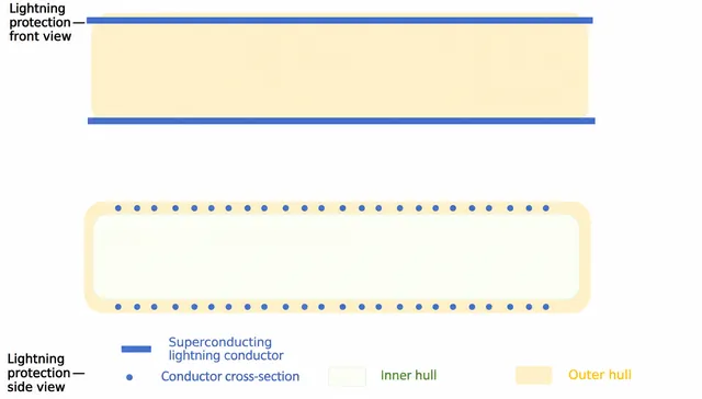
Figure 5. Front and side views of the lightning protection assembly. Superconducting conductors with large cross-sections run north–south across the upper and lower surfaces of the hull.
Table 17. Superconducting lightning conductor design
| Item | Value | Notes |
|---|---|---|
| Cross-section per conductor | 1 dm² (100 cm²) | Assumed |
| Current density under the lightning envelope | 3×10⁶ A/cm² | A factor of 30–300 below the assumed $J_{c}$ |
| Orientation | North–south, straight across the upper and lower surfaces | Current parallel to B; zero Lorentz force |
| Arrangement | 120 pairs, approximately 100 m apart | Assumed |
| Total mass | Approximately 5,200 metric tonnes | Less than 0.1% of the available hardware mass budget |
The orientation of these conductors matters: only straight north–south segments experience no force. If a conductor wraps around the hull, the vertical segments along its sides experience an east–west force. The lightning conductors must also be electrically isolated from the lift circuits, with sufficient clearance to prevent flashover; otherwise, lightning could still jump across.
12. Structure: the sandwich gap bears the magnetic pressure—and the final bill
Currents in the outer layer flow in the same direction and attract one another; currents in the inner and outer layers flow in opposite directions and repel one another. The latter force is twice the former, so the net result is that the outer layer is pushed outward and the inner layer is pressed inward. This reverses the picture of a crushed drink can that applies when considering only a single current layer.
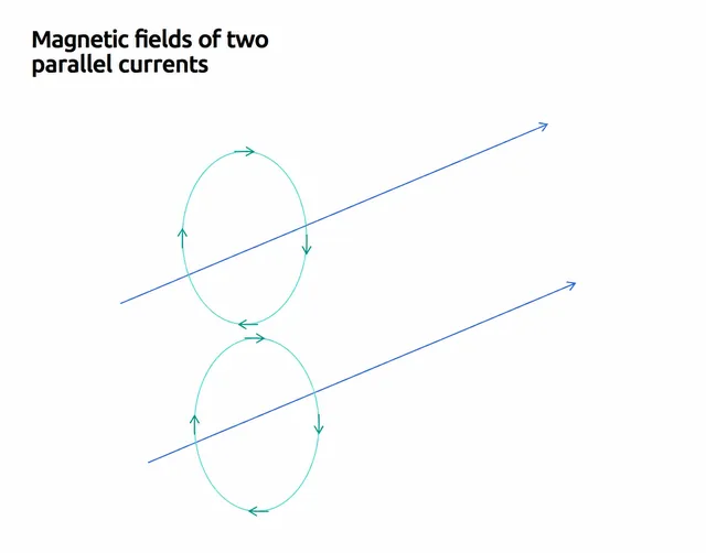
Figure 6. Magnetic fields around two currents flowing in the same direction. The fields oppose one another between the conductors and add together on their outer sides, so currents within the same layer attract one another.
The magnetic pressure is:
This is equivalent to approximately 1,160 atmospheres, slightly more than the pressure at Challenger Deep (approximately 1,100 atmospheres). But the analogy ends there: a deep-sea submersible uses a spherical shell a few meters across, whereas this is a cylinder 2 km in diameter. If circumferential tension in the outer layer were to carry the load, the required wall thickness t = $P_{m}$R/σ would be approximately 5.7 m at 20 GPa. The hull would weigh approximately 600 million metric tonnes—60 times the city payload.
The solution is to connect the inner and outer layers with tie rods, rather than make the shell carry the load. The outward and inward forces are equal and opposite, and radial tie rods spanning the sandwich gap balance them directly. The structural mass then approaches the lower bound set by the virial theorem:
Table 18. Trade-offs between sandwich gap thickness and tie-rod material (nominal 118 MPa)
| Gap Δ | Magnetic energy $E_{B}$ (J) | Cutoff momentum (GeV/c) | 3.5 GPa carbon fiber (10,000 metric tonnes) | 10 GPa (10,000 metric tonnes) | 20 GPa (10,000 metric tonnes) | 50 GPa (10,000 metric tonnes) |
|---|---|---|---|---|---|---|
| 10 m | 8.67×10¹⁶ | 51.6 | 4,460 | 1,390 | 650 | 260 |
| 5 m | 4.33×10¹⁶ | 25.8 | 2,230 | 693 | 325 | 130 |
| 3 m | 2.60×10¹⁶ | 15.5 | 1,340 | 416 | 195 | 78 |
| 2 m | 1.73×10¹⁶ | 10.3 | 891 | 277 | 130 | 52 |
| 1 m | 8.67×10¹⁵ | 5.2 | 446 | 139 | 65 | 26 |
The table uses ρ = 1,800 kg/m³ for carbon fiber and 1,500–1,600 kg/m³ for the other materials; all allowable stresses are assumed. An allowable stress of 20 GPa exceeds the strength of present-day carbon fiber. It is the second material assumption, after metallic hydrogen. At this value, tie rods occupy only 0.6% of the sandwich gap. The inner and outer hulls still retain a 10 m separation, with the remaining space reserved for cooling, maintenance access, and shielding. Scaling the tie rods for the peak condition of 134 MPa gives a mass of approximately 1.48 million metric tonnes.
Table 19. Overall mass budget
| Item | Mass (10,000 metric tonnes) | Basis |
|---|---|---|
| City payload | 1,000 | Assumed |
| Lift conductors + return conductors + shielding tubes (8.4 million circuits, k = 3) | 212 | Calculated |
| Tie rods spanning the sandwich gap (20 GPa, 134 MPa condition) | 148 | Calculated |
| Endcap magnetic plugs (conductors + tie rods) | 22 | Calculated |
| Lightning conductors | 0.5 | Calculated |
| Remaining: cooling, radiators, propulsion, power generation, and design margin | Approximately 326 | Calculated; 19% of total mass |
| Total (= total lift / g) | 1,708 | Calculated |
The budget closes, but it also exposes the most sensitive item. If the tie-rod material offers only 10 GPa, tie-rod mass rises to approximately 3.15 million metric tonnes, reducing the margin from 3.26 million to approximately 1.60 million metric tonnes. With carbon fiber at only 3.5 GPa, the tie rods weigh approximately 10.10 million metric tonnes, and the budget no longer closes.
13. Operations: the flux pump needs surprisingly little power
A superconductor has zero DC resistance, but small joint resistances and flux creep still cause the current to decay slowly. Assume an annual decay rate of 0.001%:
The entire spacecraft's losses amount to only approximately 11 kW. Supplying that power—comparable to a home EV charger—is enough to maintain 1.73×10¹⁶ J of stored energy. Without compensation, the city would descend by only approximately 0.8 m per year. This also sets a demanding fabrication requirement: the equivalent resistance of each circuit must remain below approximately 13 pΩ. If the joint resistance reaches 1 nΩ, the annual decay rate becomes 0.076%, 76 times the assumed value.
A flux pump is a small superconducting device mounted on the circuit. It uses an alternating magnetic field like a ratchet to “pump” current into the main circuit without opening it. It also acts as the actuator for the active damping discussed in section 7, so its actual specification must be determined by the required control bandwidth, rather than by this 11 kW figure.
14. Quenching: magnetic energy is the match, metallic hydrogen is the explosive
The quench sequence is as follows: superconductivity is lost locally, resistance rises sharply, magnetic energy becomes heat, the lattice destabilizes, and metallic hydrogen recombines into H₂. The theoretical recombination energy is approximately 216 MJ/kg, approximately 50 times that of TNT. This is chemical energy, not nuclear energy. It will not trigger fusion, but it is enough to destroy the hull.
Table 20. Energy comparison
| Object | Metallic hydrogen recombination energy | Magnetic energy |
|---|---|---|
| One 1 cm² lift conductor (840 kg) | 1.8×10¹¹ J, approximately 43 metric tonnes of TNT | — |
| One 0.1 cm² lift conductor (84 kg) | 1.8×10¹⁰ J, approximately 4.3 metric tonnes of TNT | — |
| One circuit (k = 3, 252 kg) | 5.4×10¹⁰ J, approximately 13 metric tonnes of TNT | 2.1×10⁹ J, approximately 0.49 metric tonnes of TNT |
| Entire spacecraft | 4.6×10¹⁷ J, approximately 109 Mt TNT | 1.7×10¹⁶ J, approximately 4 Mt TNT |
The chemical energy of all the metallic hydrogen aboard is 26 times the magnetic energy. Protection must therefore focus on stopping the recombination reaction from propagating between regions, rather than on absorbing the magnetic energy. Reducing the cross-section from 1 cm² to 0.1 cm² also reduces the “explosive charge” in each conductor to one-tenth. There are currently no data on the activation energy required to initiate recombination or its propagation speed. These are the first questions material testing must address.
Table 21. Principal failure modes
| Failure | Trigger | Consequence | Design response |
|---|---|---|---|
| Single-circuit quench | Local hot spot, radiation damage, joint defect | Local explosion equivalent to approximately 13 metric tonnes of TNT | Circuit segmentation, blast-resistant compartments, isolation between circuits |
| Cascading quench | Simultaneous failure of shared cooling, power, or control | Up to 109 Mt equivalent; destruction of the city | Zoned cooling and control; isolation against common-cause failures |
| Overtemperature | Descent beyond 6 bar, or heat leakage from radiators to conductors | Reduced $J_{c}$, triggering a quench | Temperature interlocks, forced ascent, thermal isolation of radiators |
| Sudden loss of 1% of lift | Approximately 80,000 circuits drop out simultaneously | Approximately 819 m of descent and sustained oscillation | Automatic compensation through magnetic flux linkage in the remaining circuits; active damping |
| Lightning enters a lift conductor | Breakdown of the lightning protection system | Local J > $J_{c}$; quench | Insulation clearance; lightning conductors conduct first |
| North–south propulsion failure | Thruster failure | Drift away from the magnetic equator with a time constant of approximately 20 minutes | Redundant propulsion; aerodynamic surfaces as backup |
| Tie-rod failure | Fatigue, radiation damage, overpressure | Local coil instability, potentially triggering a quench | Redundant tie rods, strain monitoring, current limits |
| Failure to reverse current beyond synchronous orbit | Flux pump failure | Premature release into an unplanned orbit | Nonfatal; retain orbit-insertion Δv and maneuvering margin |
15. How this design can be tested
A design is not complete until it can be rejected by a test. The following criteria are examples intended to show what each stage should measure.
Table 22. Test sequence
| Stage | What to verify | Exit criteria (examples) |
|---|---|---|
| 0. P1 tabletop experiment | Net force on a shielded circuit in a uniform field. I = 100 A, L = 1 m, B = 0.1 T, measured on a torsion balance | P1 predicts 10 N; classical physics predicts 0. A measurement below 1 mN rejects P1, redirecting the entire design to Route C |
| 1. Metallic hydrogen sample | Metastability at ambient pressure, $T_{c}$, $J_{c}$, lifetime, and recombination propagation | Remains stable at 300 K; $J_{c}$ ≥ 10⁶ A/cm² in 17 T; lifetime ≥ 30 years |
| 2. Coil assembly | 2 m sandwich gap, 17 T, 134 MPa, tie-rod fatigue | Tie-rod allowable stress ≥ 20 GPa; stiffness loss < 5% after 1,000 cycles |
| 3. Long-duration circuit | Joint resistance, flux creep, flux pump | Annual drift < 0.001%; R < 13 pΩ per circuit |
| 4. Jupiter pathfinder | Route C at the 200–600 metric tonne scale; measurements of ionospheric conductance, magnetic equatorial corridors, and radiation spectra | Lift predicted by the model based on measurements agrees within < 10% |
| 5. Hovering at 1 bar | Magnetic spring and damping of a city-scale section | A 1% payload change produces an offset of 819 m ± 10%; period 361 s ± 10%; oscillations decay within 3 cycles |
| 6. Ascent and release | Co-rotation ascent, angular momentum transfer, current crossing zero, heat rejection | Peak current agrees with the model within ±5%; post-release apoapsis error < 1% |
Stage 0 costs little, but determines the direction of the entire design. It belongs first and is the only stage that can be attempted now.
Jupiter's magnetic field offers a route, but every leg comes with a bill: the circuit must close, the mass budget must close, waste heat needs somewhere to go, and failures need an escape route. A fictional setting can send a spacecraft to Jupiter; whether we can finish the accounting determines how much it resembles a real spacecraft.
References and calculation basis
- NASA NSSDC, Jupiter Fact Sheet: mass, radius, rotation period, and gravitational parameter.
- Connerney et al. (2022), A New Model of Jupiter's Magnetic Field at the Completion of Juno's Prime Mission, JGR Planets 127: the JRM33 magnetic field model.
- Seiff et al. (1998), Thermal structure of Jupiter's atmosphere near the edge of a 5-μm hot spot in the north equatorial belt, JGR 103: temperature and pressure profiles.
- Silvera & Cole (2010), Metallic hydrogen: The most powerful rocket fuel yet to exist: recombination energy and specific impulse.
- Loubeyre, Occelli & Dumas, Observation of a first order phase transition to metal hydrogen near 425 GPa; 2022 experimental preprint: the experimental status of metallic hydrogen.
- F. C. Moon, The Virial Theorem and Scaling Laws for Superconducting Magnet Systems: the lower bound on magnet structural mass.
- Neubauer (1980), Nonlinear standing Alfvén wave current system at Io: Theory; SKA review (approximately 1 MA); analysis of Galileo observations (approximately 3 MA): the Io current system.
- Galileo Images of Lightning on Jupiter (1999): optical energy of lightning.
- J. D. Jackson, Classical Electrodynamics: the force on a magnetic dipole, F = ∇(m·B), and the multipole expansion of current distributions.
- Scienshell, Helium-3 Mining at Jupiter; Engineering Cybernetics of the Aerostat City: the fuel network and aerostat cities in the same fictional setting.
- Constants used: GM = 1.26687×10¹⁷ m³/s², r₀ = 71,492 km, B₀ = 4.2 G, rotation period 9.925 h, μ₀ = 4π×10⁻⁷ H/m. The calculations use spherically symmetric gravity and a pure dipole field, omitting J₂ and higher-order magnetic moments. As a result, the co-rotation effective load of 22.58 m/s² is approximately 2% below the measured effective equatorial gravity of 23.12 m/s².
Appendix A. Principal symbols
Table 23. Symbols
| Symbol | Meaning | Symbol | Meaning |
|---|---|---|---|
| I | Current per circuit | $B_{gap}$ | Self-generated magnetic field in the sandwich gap |
| L | Conductor length (12 km) | Δ | Coil sandwich gap thickness |
| A | Conductor cross-sectional area | $P_{m}$ | Magnetic pressure |
| J / $J_{c}$ | Current density / critical current density | $E_{B}$ | Magnetic energy |
| k | Total circuit mass / lift conductor mass | $L_{s}$ | Equivalent inductance per circuit |
| N | Number of circuits | ω | Jupiter's angular rotation rate |
| $M_{p}$ / M | City payload / total mass | $r_{s}$ | Synchronous orbit radius |
| a(r) | Effective load acceleration in the co-rotating frame | ΔΦ | Effective potential difference |
| m | Magnetic moment | λ | Magnetic latitude |
| σ / ρ | Allowable stress / density | $r_{L}$ | Gyroradius |