
Receive, Transform, Release: Turning a Gamma-Ray Power Beam Back into Electricity
A hard-science-fiction engineering estimate of the receiving end of an interplanetary power beam: pair-production foils, magnetic separation, ±99 MV depressed collectors and the efficiency of the whole chain from Mercury.
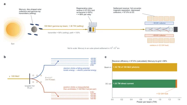
From Mercury's collectors to a settlement's grid: the receiving end of an interplanetary gamma-ray power beam.
A gamma-ray beam crosses the Solar System and, at the end of its path, has to become electricity again in front of a settlement. An ordinary solar panel is useless against it. A 100 MeV photon either passes straight through the panel or shatters it. Catching such a beam takes a machine that turns photons into matter and then turns the motion of that matter into voltage.
In Solar Grid, the second film of the Out of the Cradle series, Mercury's solar collectors feed an interplanetary network of gamma-ray beams. The companion article, The Source of All Rivers, follows the transmitting end on Mercury. This article follows the other end: it starts from why the beam is dangerous, then works through the converter, the magnetic separation, the collectors and the efficiency of the whole chain.
How the argument is built: three kinds of basis
- Established physics (not negotiable): pair production, radiation length, the motion of charged particles in magnetic and electric fields, positron annihilation.
- Extrapolation of existing technology (adopted for the setting): multistage depressed collectors, which are standard in travelling-wave tubes, and the direct energy converters studied for fusion reactors.
- Engineering extrapolation (setting): vacuum DC electrodes at about 100 MV and converter arrays hundreds of metres long.
Numbers are labelled as calculation, assumption or setting where it matters. The beam power of 1.36 TW and the transmitter efficiency of about 90% are setting values taken from the transmitter article.
The main findings
To a gamma beam, the human body is transparent and still lethal. A 100 MeV photon travels on average about 56 cm in tissue before it interacts. Crossing a torso 20–30 cm thick, roughly a third of the photons interact inside the body and the rest pass straight through. Every interaction releases electrons and positrons of tens of MeV deep inside the tissue.
The receiver is a stack of thin foils. Each tungsten foil, about 35 μm thick, converts about 0.58% of the photons into electron–positron pairs at 100 MeV. About 800 foils in series convert 99%. A magnetic field pulls each pair out of the beam as soon as it is made.
The particles climb a voltage directly. Electrons and positrons run into collectors held at up to −99 MV and +99 MV. As they climb, their kinetic energy turns into electric potential energy, with no heat engine in between.
The receiver efficiency is about 97.5%. The main losses are the 1% of photons that pass every foil (to a beam dump), the rest mass of the pairs, which ends up as annihilation radiation (1.0%), bremsstrahlung in the foils (0.25–0.5%) and the collector's voltage steps (0.1%).
From Mercury's electrical bus to the settlement's grid, about 88% arrives: about 90% at the transmitter times about 97.5% at the receiver. Each regenerative relay on the way multiplies by about 88% again.
Table 1. Receiver design baseline
| Parameter | Value | Basis |
|---|---|---|
| Incoming photons | 100 MeV, 1.36 TW per beam | Setting, from the transmitter article |
| Converter | About 800 tungsten foils, each 0.01 $X_0$ (35 μm), 1 m apart | Calculation |
| Conversion per foil | About 0.58% at 100 MeV (0.78% in the high-energy limit) | Calculation |
| Separation field | About 0.2 T (a 50 MeV electron bends with radius 0.84 m) | Calculation |
| Collector voltage | ±99 MV (more precisely ±98.98 MV), multistage depressed collection in 100 kV steps | Setting / calculation |
| Collected current | About 13.5 kA per polarity | Calculation |
| Receiver efficiency | About 97.5% | Calculation |
| Heat per beam | About 32–36 GW | Calculation |
1. Catching a bullet
A 100 MeV photon carries far more energy than the 1.022 MeV needed to create an electron–positron pair. In matter its main interaction is pair production. At very high energy, the mean free path for pair production tends to 9/7 of the radiation length $X_0$:
At 100 MeV the pair cross-section has not yet reached that limit: it is about 70% of it in water and 75% in tungsten. Compton scattering adds a little. The real mean free path is therefore about a quarter longer than the textbook 9/7 $X_0$.
Table 2. A 100 MeV photon in three materials
| Material | Radiation length $X_0$ | 9/7 $X_0$ (high-energy limit) | Mean free path at 100 MeV | What it means |
|---|---|---|---|---|
| Human tissue (water) | 36.1 cm | 46 cm | About 56 cm | 30–41% of photons interact in a 20–30 cm torso; the rest pass through |
| Titanium | 3.56 cm | 4.6 cm | About 5.9 cm | A 3 cm hull converts about 40% of the beam into particle showers inside the ship |
| Tungsten | 0.350 cm | 0.45 cm | About 0.59 cm | Densest practical converter |
Radiation lengths from the Particle Data Group. The 100 MeV column uses the screened Bethe–Heitler pair cross-section plus Klein–Nishina Compton scattering (calculation; see Figure 1).
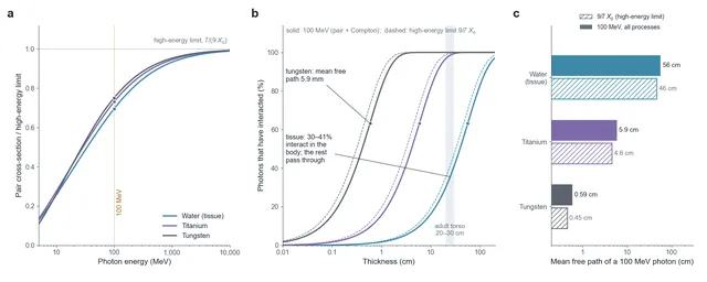
Figure 1. How 100 MeV photons interact with matter (calculated). a, Pair-production cross-section as a fraction of its high-energy limit for water, titanium and tungsten: at 100 MeV it is still only 70–75% of the limit. b, Fraction of photons that have interacted against thickness; solid lines include the real 100 MeV cross-section and Compton scattering, dashed lines use the high-energy limit; dots mark one mean free path. A 20–30 cm torso stops only 30–41% of the beam. c, Mean free paths at 100 MeV compared with the textbook 9/7 X0.
The body is almost transparent to this light, and that is exactly the problem. Pairs are created at every depth. Each particle carries on average about 49.5 MeV of kinetic energy, so each pair carries about 99 MeV. Along their tracks they ionise atoms and break chemical bonds, and the positrons finally annihilate with electrons in the tissue. The mechanism is the same ionisation as any other radiation, but a terawatt beam delivers it at a rate that kills at once, from the inside. The receiver therefore has one job: light goes in, and only electricity comes out.
2. Pair production: turning light into matter
In the strong electric field near a heavy nucleus, a photon turns into an electron and a positron:
Of the 100 MeV, 1.022 MeV becomes the rest mass of the two particles. The remaining 98.98 MeV is their kinetic energy, shared between them at random: an even split is common, but so is a split such as 10 and 89 MeV (Figure 2c). The pair travels almost exactly along the photon's original direction. The characteristic angle of each particle is about $m_ec^2/E$, about 0.01 rad for a 50 MeV particle. Multiple scattering on the way out of the foil adds a comparable spread, about 0.015 rad. Both are small.
3. Why a stack of thin foils
A single thick tungsten block would not work. The pairs would keep radiating photons inside the block, the photons would make new pairs, and the energy would end up in thousands of low-energy particles and heat. This is an electromagnetic shower, and it cannot be collected. The converter is therefore a stack of thin foils:
Here $\sigma/\sigma_\infty\approx0.75$ is the ratio of the tungsten pair cross-section at 100 MeV to its high-energy limit. With the high-energy limit, each foil would convert 0.78% and about 590 foils would reach 99%; at 100 MeV the same 600 foils convert only 97% and send 3% of the beam, about 41 GW, into the beam dump. The design therefore uses about 800 foils.
Each foil converts less than 1% of the photons. A pair made in a foil leaves it at once and enters the next stretch of vacuum, where a magnetic field steers it out of the beam path so that it never crosses the foils behind. With about 1 m of field between neighbouring foils, the converter is about 800 m long. This is the physical reason why the receiver in the film is a long structure.
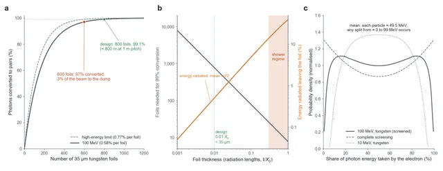
Figure 2. Designing the foil stack (calculated). a, Cumulative conversion against the number of 35 μm tungsten foils, at the real 100 MeV cross-section (solid) and in the high-energy limit (dashed); 600 foils reach 97%, 800 foils 99.1%. b, The thickness trade-off: thinner foils need more of them, thicker foils lose more energy to bremsstrahlung as the particles leave (mean loss about t/2 in radiation lengths); near one radiation length the converter becomes a shower. c, How the photon energy is shared between electron and positron at 100 MeV in tungsten, compared with the complete-screening limit and with 10 MeV photons.
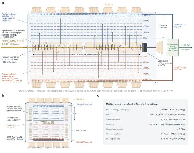
Figure 3. The receiver (schematic; setting with calculated values). a, Elevation: the gamma beam enters from the left and crosses about 800 tungsten foils; between the foils a 0.2 T dipole field bends electrons up and positrons down into two stacks of collector grids, falling to −98.98 MV for electrons and rising to +98.98 MV for positrons. Each track ends on the grid whose potential equals the particle's kinetic energy. Photons that pass every foil stop in the beam dump. The two terminals feed a DC converter station; radiators reject about 32–36 GW of heat. b, Cross-section looking along the beam: dipole poles beside the beam, grids held by stacked insulator columns, at least 10 m of vacuum between 0 and 99 MV, and a shield for the annihilation radiation behind the positive terminal. c, Design values.
4. Magnetic separation
Electrons and positrons have opposite charges, so the same magnetic field bends them in opposite directions. The bending radius of a 50 MeV electron in a 0.2 T field is:
with $p$ in GeV/c, $B$ in tesla and $r$ in metres. A field of 0.17 T would give exactly 1 m. Within 30 cm of the foil, an evenly split pair is already about 11 cm apart. Annihilation between the two partners in flight is negligible in any case; what matters is that each particle is steered out of the beam before it reaches the next foil. The electron stream and the positron stream then enter the collector channels on either side. The field does no work on the particles, and at these energies the synchrotron radiation in 0.2 T is a fraction of an electronvolt per particle.
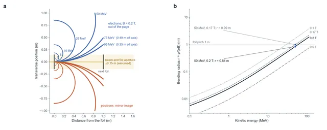
Figure 4. Magnetic separation (calculated). a, Paths of electrons (blue) and positrons (red) of 2 to 95 MeV leaving a foil in a 0.2 T field, to scale. Particles below about 60 MeV turn through more than a right angle within the 1 m to the next foil; the most energetic ones are only 0.35–0.5 m off axis there, so the foils and the beam must be narrower than this. b, Bending radius against kinetic energy for fields of 0.1, 0.17, 0.2 and 0.5 T.
Two details follow from the figure. First, the 95 MeV particles have the largest radius, about 1.6 m, and drift only 0.35 m sideways before the next foil; the foil and beam aperture must stay within about ±0.15–0.3 m, or the field section must be longer. Second, the slowest particles, below a few MeV, curl up with radii of a few centimetres and some will strike the foil they came from. They carry little of the energy.
5. Depressed collectors: making electrons climb a voltage
The collector is two sets of electrodes. Electrons run towards grids whose potential falls step by step to −99 MV; positrons run towards grids that rise to +99 MV. A particle climbing this slope turns its kinetic energy into potential energy and is caught on the grid where its kinetic energy runs out:
The highest grid has to stop the most energetic particle possible. That is a particle that took all 98.98 MeV of the pair's kinetic energy, so the terminals sit at ±98.98 MV, rounded to ±99 MV in the text. The voltage between the two terminals is 197.96 MV. The charge that arrives forms a DC source directly: about 13.5 kA flows in each polarity, landing at an average potential of about 49.5 MV (Figure 5a).
This is a multistage depressed collector. Travelling-wave tubes, for example in communication satellites, use the same principle to recover the energy of their spent electron beam, and the direct energy converters proposed for fusion reactors work in the same way. The finer the steps, the less energy each particle loses when it lands on the grid just below its own energy. A particle loses between zero and one full step, on average half a step.
Table 3. Collector step size and staging loss
| Voltage step | Grids per side | One 30 MeV electron, worst case | One 30 MeV electron, average | Whole spectrum, average |
|---|---|---|---|---|
| 1 MV | 99 | 1 MeV (3.3%) | 1.7% | 1.0% |
| 100 kV | 990 | 100 keV (0.33%) | 0.17% | 0.10% |
| 10 kV | About 9,900 | 10 keV (0.033%) | 0.017% | 0.010% |
| 1 kV | About 99,000 | 1 keV (0.003%) | 0.002% | 0.001% |
Calculation. "Whole spectrum" averages over the screened Bethe–Heitler energy-sharing distribution at 100 MeV; its mean kinetic energy per particle is 49.5 MeV, and the mean loss per particle is half a step. The design uses 100 kV steps.
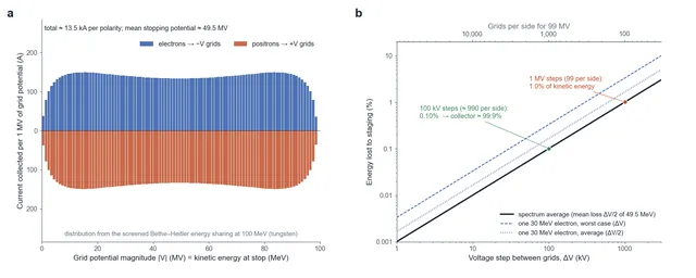
Figure 5. The depressed collector (calculated). a, Current collected per 1 MV of grid potential for one 1.36 TW beam: electrons on the negative grids, positrons on the positive grids; the shape follows the energy-sharing spectrum of Figure 2c. b, Energy lost to staging against the voltage step, for the whole spectrum and for a single 30 MeV electron; the top axis gives the number of grids needed per side.
The staging loss is only part of a real collector's losses. Particles that arrive at an angle carry part of their energy sideways, where the retarding field cannot recover it, and particles that reach a grid at low energy knock out secondary electrons or bounce back. The best travelling-wave-tube collectors today recover roughly 80–90% of the spent-beam energy, and fusion direct-converter experiments reached lower values. The 99.9% used here is the staging limit alone and is an engineering extrapolation (setting). It is the largest single uncertainty in the receiver's efficiency.
A potential of 99 MV in vacuum also needs room. At an assumed breakdown gradient of about 10 MV/m, the electrodes need at least 10 m between 0 and 99 MV (setting). This is optimistic: across gaps of metres, the voltage that vacuum can hold grows more slowly than the gap, and today's largest electrostatic accelerators run at roughly 1–2 MV per metre along their columns, in insulating gas rather than vacuum. The collected charge forms a DC supply of about 100 MV per pole, which a converter station steps down and feeds into the settlement's grid. The losses in that station are not counted here.
6. The efficiency ledger
Table 4. Energy budget of the receiver (one beam)
| Stage | Where | Mechanism | Share of beam | Power per 1.36 TW beam |
|---|---|---|---|---|
| Unconverted photons | Beam dump | About 0.9% of photons pass all 800 foils | 0.94% lost | 12.7 GW |
| Pair rest mass | Positive collector | 1.022 MeV per pair becomes rest mass; each positron annihilates into two 0.511 MeV photons | 1.01% lost | 13.8 GW |
| Foil bremsstrahlung | Converter | About 0.5% radiated as particles leave their foil; roughly half of it assumed to reconvert in later foils | 0.25–0.5% lost | 3.3–6.6 GW |
| Foil ionisation | Converter | About 0.085 MeV per pair deposited in the foil | 0.08% lost | 1.1 GW |
| Magnetic deflection | Dipole sections | A magnetic field does no work | About 0 | — |
| Collector staging | ±99 MV grids, 100 kV steps | Half a step lost per particle on average | 0.10% lost | 1.3 GW |
| Total | — | — | 2.4–2.6% lost; efficiency about 97.5% | 32–36 GW |
Calculation. The collector line is the staging limit only; see Section 5 for the larger real-world losses that the setting assumes away. DC conversion at the settlement is not included.
A beam of 1.36 TW comes in and about 1.33 TW of direct current goes out. About 32–36 GW becomes heat, removed by the receiver's radiators. Much of it arrives as hard radiation, not as warm metal: nearly 13 GW of 100 MeV photons in the beam dump and nearly 14 GW of 0.511 MeV annihilation photons at the positive collector. Both need shielding as well as cooling.
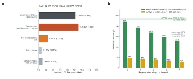
Figure 6. Power budget and transmission chain (calculated). a, Where the heat goes for one 1.36 TW beam: unconverted photons in the beam dump, annihilation of the pairs' rest mass at the positive collector, bremsstrahlung and ionisation in the foils, and collector staging; about 1.33 TW leaves as direct current. b, Delivered fraction against the number of regenerative relays: electric to electric (Mercury bus to settlement grid) and sunlight to grid, compared with today's ultra-high-voltage DC lines over 2,000–3,000 km.
Compared with ordinary photovoltaics:
Table 5. Two ways of turning light into electricity
| Item | Solar photovoltaics | Gamma-ray receiver |
|---|---|---|
| Photon energy | About 1–3 eV | 100 MeV |
| Output voltage (DC) | About 1–1.5 kV per string | About ±99 MV |
| Light-to-electricity efficiency | About 20–25% (commercial modules) | About 97.5% |
| Principle | Photoelectric effect across a semiconductor band gap | Pair production plus direct energy conversion |
7. The whole transmission chain
Table 6. From sunlight to a settlement's grid
| Step | Efficiency | Cumulative |
|---|---|---|
| Sunlight → electricity (Mercury's disc-shaped collectors) | About 22% (setting) | 22% |
| Electricity → gamma rays (transmitter) | About 90% (setting) | About 20% |
| Beam path | About 100% | About 20% |
| Gamma rays → electricity (receiver) | About 97.5% | About 19% |
| Each regenerative relay on the way | × about 88% | — |
A regenerative relay receives the beam (97.5%) and transmits it again (90%). Interplanetary gas is far too thin to absorb the beam: the solar-wind column over 1 AU is about 10⁻¹⁰ g/cm², against 63 g/cm² for one radiation length of hydrogen. Keeping the beam narrow and on target over that distance is a transmitter problem (setting).
From Mercury's electrical bus to the settlement's grid, about 88% of the electrical energy arrives with no relay, 77% with one relay and 68% with two (Figure 6b). The direct link is a little below today's best ultra-high-voltage DC lines, which deliver roughly 92–95% over 2,000–3,000 km. But the beam covers hundreds of millions of kilometres. Sunlight itself is inexhaustible; what is valuable is a chain that gathers it where it is plentiful and delivers it where it is needed.
8. Main failure modes
Table 7. Failures and responses
| Failure | Trigger | Consequence | Design response |
|---|---|---|---|
| Unconverted photons | Conversion below design | About 1% of the beam (13 GW) passes the stack; more if foils are missing | Thick absorber behind the receiver |
| Vacuum breakdown | Discharge at the 99 MV electrodes | Collection interrupted | Segmented electrodes; automatic voltage reduction after a breakdown |
| Foil damage | Heat load and radiation | Conversion falls | Replaceable foil modules; the first foils absorb several MW each from ionisation alone |
| Magnet failure | Coil fault | Pairs strike the walls and the foils behind, starting showers | Interlock shutdown; the transmitter stops firing |
| Personnel in the beam line | Error in a maintenance procedure | Lethal exposure | Interlock confirmation before the beam arrives |
No roar of a heat engine, no spinning turbine. A photon becomes a pair of particles beside a tungsten nucleus, the particles climb a slope of a hundred megavolts, and the light has become electricity. Mercury is the heart, the light nodes are the blood vessels and the gamma rays are the blood: humanity has become a civilisation that feeds on light.
References and calculation basis
- Particle Data Group, Passage of particles through matter, and Atomic and Nuclear Properties of Materials: pair production, radiation lengths (water 36.08 g/cm², titanium 16.16 g/cm², tungsten 6.76 g/cm²), bremsstrahlung and multiple scattering.
- Tsai (1974), Pair production and bremsstrahlung of charged leptons, Reviews of Modern Physics 46: screened Bethe–Heitler cross-sections.
- Kosmahl (1982), Modern multistage depressed collectors: a review, Proceedings of the IEEE 70: multistage depressed collectors.
- Moir and Barr (1973), Venetian-blind direct energy converter for fusion reactors, Nuclear Fusion 13: direct energy conversion.
- Scienshell, The Source of All Rivers: the Mercury transmitter, 1.36 TW per beam and the transmitter efficiency.
- Calculation basis: 100 MeV photons; tungsten foils of 0.01 $X_0$; pair cross-section from the Bethe–Heitler formula with Thomas–Fermi screening and the Coulomb correction, normalised to the PDG high-energy limit; Klein–Nishina Compton scattering; collision stopping power of tungsten for 50 MeV electrons about 1.25 MeV cm²/g; bending radius from the exact momentum of the particle. A vacuum breakdown gradient of about 10 MV/m and the 99.9% collector efficiency are setting values.